TLE: Drafting 100 Items

1.When a designer or an ordinary person translates his or her own design idea with the use of paper and pencil, what is the name of the activity?
A. Architectural delineation
B.Freehand Sketching
C.Geometric Construction
D.Drafting
2.After two dimensional drawings are done and all the shapes and sizes being laid-out, the next step to be executed to complete the process is_.
A.Dimensioning
B.Tolerancing
C.Specifications
D.Sectional Drawing
3.With the help of drawing instruments such as T-square and triangles, one produces quick and accurate delineations for an intended project. The process is considered as:
A. Drafting
B. Pictorial Drawing
C. Graphics
D. Shape and Size Descriptions
4.Technical drafting involves the manipulation of the elements of geometry to make accurate description of shapes. Which term is referred to by engineering’s and drafting professionals all over world?
A. Blueprint Reading
B. Geometric Construction
C. Line Weight
D. Measurement
5.Objects to be drawn are not always solid in nature and if we want to explain complex objects to the reader of our blueprints we need an imaginary cut through the component or an assembly drawing to portray exactly what is inside. This element is called:
A. Sectioning
B. Parallel Perspective
C. Etching
D. Dimensioning
6.To make drawings look more professional, the notes, dimensions, and other specifications must be professionally executed. In manual drafting this is called:
A. Lettering by the hand
B. Scaling
C. Drawing of views
D. Legibility
7.In various engineering fields, multiple line weights are being to emphasize areas of drawing. It is also standardized in order for a uniform interpretation drawing. The term is called:
A. Horizontal Line
B. Center line
C. Alphabet lines
D. Dimensioning
8.It is about placing units of measure to the height, width, and length of an object to convey accurate instructions to part. In old English it is called “dimensions”. IN drafting this means:
A. Tolerance
B. Datum
C. axis
D. dimensioning
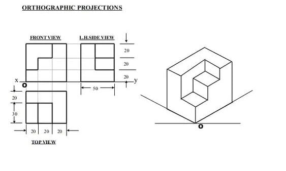
9.Which is a method of
representing the exact shape and size of an object drawn to scale on “set of planes” which sometimes are called planes of projection? It is also known as 3-view drawing.
A. Orthographic Projection
B. Perspective Construction
C. Isometric Drawing
D. Fourth Dimension
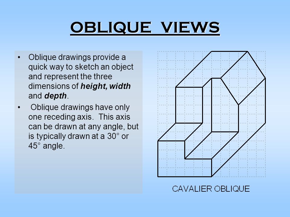
10.Which technique in pictorial drawing appears like 3-dimensional but the lines are exactly 30 degrees from horizontal part of the object?
A. Isometric Drawing
B. Cabinet Drawing
C. Oblique Drawing
D. Perspective Drawing
11.As far as the appearance of the drawing is concerned, it is the most important part for the usefulness of the drawing it can be ruined if it is done carelessly:
A. Painting
B. Lettering
C. Etching
D. Calligraphy
12.There are six secrets of lettering namely: form, proportion, stability, density, and spacing. Identify the sixth secret by completing the adage: “A good draft man will never letter without use of:
A. Line
B. Guidelines
C. Horizontal lines
D. Border lines
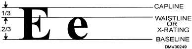
13.Five guidelines are accepted in the drafting field. Which of them are laid-out to touch the capital letter c aside from the base line?
A. Base line
B. Cap line
C. Drop line
D. Waist line
14.Which of these are positioned to limit letter g aside from waist line?
A. Base line
B. Cap line
C. Drop line
D. Waist line
15.Of the many styles of letters, the most commonly used are script or italics, gothic, old English and roman. Which of them is most commonly used in college diploma?
A. Roman
B. Script or italics
C. Old English
D. Gothic
16.Time is gold so a drafter must not get into a habit of making excessively time-consuming letters. Single-stroke letters are advised with:
A. Rapidity of stroke
B. Sloppiness
C. Laziness
D. Free and natural
17.A grade 9 student understood that the Roman letters consist of thick and thin lines and was asking to him. What were those small thin lines at the end of every letter except O? in the drafting field the lines are called:
A. Serifs
B. Stem
C. Dash line
D. Ditto
18.Prior to the introduction of Computer Aided Design and Drafting there are tools in lettering which are made of either plastic or aluminum on which the drafter just traced the letters using a technical pen to produce each letter. The instrument is called:
A. Lettering template
B. Lettering box
C. Leroy guide
D. Pressure sensitive guide
19.For beginning drafters the suggested height of letters to practice first is 6mm and then shift to a height of:
A. 30mm
B. 3mm
C. 1mm
D. 50mm
20.In the field of Drafting, each line has a specific meaning. This is to establish a uniform way when interpreting complex blueprints of objects and other mega projects. These lines are called:
A. Alphabet of Lines
B. Alpha numeric of Lines
C. Language of Lines
D. Lines of Sight
21.Based on the Blueprint, machinist is about to drill a 16mm diameter hole on a piece of 100mmx120mm flat bar. Which line in the alphabet of lines must he look for first?
A. Hidden Line
B. Phantom Line
C. Center Line
D. Section Line
22.When drawing the different views in orthographic projection, a drafter must acknowledge that there are hidden edges that must be emphasized in order to produce complete drawing information. Which line is he going to use?
A. Hidden Line
B. Section Line
C. Center Line
D. Object Line
23.A drawing teacher on a local high school was discussing a feature on which the surface appears to have imaginary cut along the cutting plane line. Which line is she going to apply to the surface where the cutting plane cut through?
A. Center Line
B. Dimension Line
C. Section line
D. invisible Line
24.There are six principal views of an object, TV, FV and RSV, RV, LSV, BV. Which the views are accepted by the industry as standard multi-views according to the 3rd angle projection?
A. Top view, front view, and right side view
B. Side view, bottom view, and rear view
C. Right side view, left side view, and bottom view
D. Front view, rear view and side view
25.A group of students is experimenting on views in orthographic projection. They extract first the front view of a simple object using a transparent material as discussed by their teacher. What technique are they using?
A. Glass box technique
B. Onion skin technique
C. Japanese paper technique
D. Polycarbonate technique
26.Orthographic projection goes farther than right angle. A drafter can actually extract views for more details of the object provided that the projectors are parallel to each other and normal to the plane of projection. The additional plane is called:
A. Frontal plane
B. Auxiliary plane
C. Profile plane
D. Horizontal plane
27.All of objects have distinct limits which can be considered as the width, depth, and height. So when a drafter is working on the difference in elevation between any two points, measured as the perpendicular distance between a pair of horizontal lines, he is now engaged in the_ of the object?
A. Depth
B. Height
C. Width
D. Bottom
28.When an engineer is engaged in the preparation of views prior to formal drafting activities, he practically bases his information on actual and accurate observation. This process is regarded as:
A. Pencil and paper exercise
B. Glass box technique
C. Orthographic sketch
D. Order drawing
29.After all the views are given, the drafter must now work on the real form of the objects based on actual result of the orthographic projection. This process is called:
A. Pictorial drawing
B. Depth dimensioning
C. Height dimensioning
D. Center dimensioning
30 In isometric drawings, the angle used to aid the construction of the object is 30 degrees and all vertical line are equal lengths or scale but in oblique drawing the angle used is:
A. 40 degrees
B. 45 degrees
C. 30 degrees
D. 60 degrees
31.In oblique drawing, the depth of the object is reduced to ½ in case of cabinet oblique, ¾ in case of a general oblique, and true or same measurement in:
A. Width
B. Cavalier
C. Specific
D. Object
32.Which technique is commonly used around the world as a graphic method or representing a 3- dimensional object and intended to combine the illusion of depth, with the undistorted presentation of the object’s principal dimension?
A. Cavalier oblique
B. Isometric drawing
C. Cabinet oblique
D. General oblique
33.When an observer stands in the middle of a street, the end of the street seems to narrow as far as his eyes can see. Then he tries to draw the buildings as it appears on his visual observations. The process is called_.
A. Perspective drawing
B. Isometric drawing
C. Diametric drawing
D. Cabinet drawing
34.A student in drafting has done three views; his next task is to indicate the dimensions to complete the information. What is the distance of the first dimension from the views?
A. 1”
B. 2”
C. 1/8”
D. ½”
35.There is a good reason why we should not place dimensions directly on the itself. This is to avoid?
A. Super dimensioning
B. Overcrowding of dimensions
C. inaccurate dimensions
D. Aligned dimension
36.The radius of an arc should always be specified by the drafter in the form of a symbol which denotes_.
A. R
B. r
C. rad
D. ra
37.It is important to the drafting students to place the overall dimension of a part or view to appear more pleasing to the reader. It is placed starting from the_.
A. Shortest dimension line outside the view
B. Longest dimension line outside the views
C. Longer dimension inside the view
D. Shorter dimension inside the view
38.Some drafter often place dimensions every while the maybe permitted in some drafting classes let us keep in mind that these are repetitions and can be avoided. This is referred to as_.
A. Superfluous dimension
B. Unidirectional dimensioning
C. Aligned dimensioning
D. Tolerance dimensioning
39.In the rule of sectional drawing, all visible edges exposed by the cutting-plane line must be emphasized and series of lines can now be drawn. This process is called_.
A. Filling-up of section lines
B. Eliminating hidden lines
C. Eliminating object lines
D. Symmetrical objects
40.There are situations in executing sectional drawings that every drafter must be familiar with especially when dealing with blow-up part of an object. We find this very reasonable with tiny and complicated parts. This refers to_.
A. Detail sections or spot details
B. Dual dimensioning
C. Aligned objects
D. Isometric objects
41.For a professional looking section detail, which additional feature shall a drafter include to really portray the drawing?
A. Line symbols
B. Common section line symbols for materials
C. Material line weight
D. Symmetric object line
42.There are several types of section- a full section which the cutting plane line passes across entire object and half section on which the cutting plane passes through an object which is_.
A. Symmetrical
B. Orthographic
C. Offset drawing
D. Common section
43.When a section is to be detailed according to the intended parts, assembly is called_.
A. Assembly of parts
B. Assembly section
C. Assembly of materials
D. Assembly of common section
44.The world has adopted the metric system of dimensioning but some countries used it voluntarily depending on the situation they practice. What is the name of their approach?
A. Unidirectional system
B. Dual dimensioning system
C. Aligned system
D. Position dimensioning
45.A third-world country even for its stage can’t neglect drafting as part of its industrial pursuit is it manual, mechanized, or automated. So a citizen of a third world country must have the necessary skill in the use of:
A. Graphic or drafting language
B. Foreign language
C. Sign language
D. English language
46.Mr. John cross purchased a 12.00m x 9.00m (frontal) land along the road. Local building code mandated that the building must have a set-back of 3.00m with respect to the edge of the paved barangay road. What then is the total area of the land minus the building code?
A. 80 square meters
B. 81 square meters
C. 90 square meters
D. 79.90 square meters
47.Grade 10 students from a local central school in the North wanted to build a square culvert with one side open for an irrigation system. The dimensions are; w=80, d=1.20, h =.80m, and the thickness is .80m. What then is the set of drawings they need before giving it to an engineer to determine the size of reinforcement bars?
A. Top view, front view, right side view, isometric
B. Top view, front view, bottom view, isometric
C. Top view, front view, rear view, isometric
D. Top view, side view
48.A half-moon protractor is divided into how many degrees?
A. 360
B. 180
C. 270
D. 310
49.A line drawn with a long section, short dash, and another long section is a_.
A. Hidden feature
B. Center of a circle
C. Center axis of a hidden cylinder
D. Center of a radius
50.Traditional drafters need to be able to create several different line widths because_.
A. Different line widths convey different information
B. The line width has to with how dark it appear in the finished drawing
C. They seem to transmit better in a fax machine
D. It makes no difference
51.Several of the tools used in traditional drafting include the following:
A. Parallel straight edge
B. 45 degrees triangle
C. Circle template
D. All the above
52.A civil engineer working on a bridge design would probably rely on his _ scale for checking printed drawings.
A. Engineer’s
B. Metric
C. Architect’s
D. None of the above
53.In order to connect fractional inches into decimal inches_____.
A. Look on a metric conversion chart
B. Divide the numerator by the denominator
C. Check the engineer’s scale
D. All of the above
54.An engineer would be used to measure lines on a drawing where the scale factor reads _____.
A. ¼” = 1’ – 0”
B. 1/8” = 1’ =0”
C. 1” = 100’
D. ¾”= 1’ 0”
55.Referring to the fractional inches to decimal inches to millimeter conversion chart on page 55 what is the equivalent mm measurement of 3/16 inch?
A. 1.906
B. 4.7625
C. 5.958
D. 14.6844
56.Some traditional board drafter preferred the drafting machine over the parallel straight edge because it could be used without the need for _____.
A. Circle template
B. Triangles
C. Technical pens
D. Lettering guides
57.The first step in creating a traditional technical drawing is to;_______
A. Draw a series of guidelines
B. Set up the miter line
C. Align the paper so that it will be positioned square to the parallel bar
D. Sharpen the leads in the technical pen
58.When lettering a CAD drawing, for clarity you should limit the number of fonts to:
A. One
B. Two
C. Three
D. Any number
59.The primary unit of measurement for engineering drawings and design in the mechanical industries is the:
A. millimeter
B. centimeter
C. meter
D. kilometer
60.These units are based on inch-foot and yard measurements:
A. international customary units
B. U.S. metric units
C. U.S. customary units
D. ISO international units
61.This is how axonometric, oblique, and perspective sketches show objects:
A. Orthographically
B. Pictorially
C. Obliquely
D. Parallel
62.This type of projection is when projectors are parallel to each other, but are at an angle other than 90 degrees to the plane of projection:
A. Oblique projection
B. Perpendicular projection
C. Aesthetic projection
D. Angular projection
63.There are two main types of projection:
A. Parallel and orthographic
B. Station-point and perspective
C. Parallel and convergent
D. Perspective and parallel
64.The top, front, and bottom and views align in this manner.
A. Horizontally
B. Vertically
C. According to the planar views
D. Parallel to the frontal plane
65.If a plane is parallel to the plane of projection, it appears;
A. True size
B. As a line or edge
C. Foreshortened
D. As an oblique surface
66.This line pattern is composed of three dashes, one long dash on each end with a short dash in the middle:
A. Object
B. Hidden
C. Center
D. Phantom
67.This is the plane upon which the top view is projected:
A. Horizontal
B. Frontal
C. Profile
D. Base
68.An advance of this type of view is that each view shows the object all the way through as if it were transparent.
A. Planar
B. Horizontal
C. Auxiliary
D. Orthographic
69.This type of surface is tipped to all principal planes of projection and does not appear true size in any standard view.
A. Foreshortened
B. Parallel
C. Orthographic
D. Oblique
70.Isometric drawings are often used by ______to help illustrate complex designs.
A. Mechanical engineers
B. Piping drafters
C. Aerospace engineers
D. All the above
71.A fillet is a rounded surface on the ___corner of a part.
A. Inside
B. Outside
C. Radial
D. Isoplane
72.A round is a rounded surface on the ___corner of part.
A. Inside
B. Outside
C. Radial
D. Isoplane
73.The bounding box method for setting up an isometric drawing helps the drafter____.
A. Confine the isometric drawing of its maximum size
B. Figure what lines are to be illustrated vertical and horizontal
C. Position isometric drawing in paper space
D. None of the above
74.The offset tool should only be used for placing_____ in an isometric drawing.
A. Circles
B. Horizontal lines
C. Vertical lines
D. None of the above
75.When creating an isometric drawing in Auto CAD, the drafter can utilize the Dynamic input and Polar Coordinate system to place both vertical and horizontal lines. A line created from one point 3 inches at 180 degrees would be a _____line.
A. Horizontal
B. Vertical
C. Inclined
D. None of the above
76.Auto CAD refers to isometric ellipses as ____
A. Ellipses
B. Isoellipses
C. Isocircle
D. Circles
77.These lines are used to indicate the measurement of objects and are represented by fine dark solid lines.
A. Leader lines
B. Extensions lines
C. Dimensions lines
D. Center lines
78.If a drawing has an equal measure then it refers to __________.
A. Perspective drawing
B. Isometric drawing
C. Mechanical drawing
D. Oblique drawing
79.When parts that are not seen are represented by series of light dash lines then this line is classified as _________.
A. Reference line
B. Visible line
C. Section line
D. Invisible line
80.One of the best practices of a good draftsman is to NEVER letter without __________.
A. Guide lines
B. Pencil
C. Lettering pens
D. Ink
81.If drawing has one surface that is parallel to the picture plane then this method is called ____.
A. Oblique drawing
B. Isometric drawing
C. Perspective drawing
D. Orthographic drawing
82.This pictorial view is normally seen by the observer’s eyes. Which one is it?
A. Isometric drawing
B. Oblique drawing
C. Perspective drawing
D. Orthographic drawing
83.The line used to show clearly the dimension limits as called ____?
A. Center line
B. Extension line
C. Dimension line
D. Phantom line or section line
84.A horizontal line used to determine the general height of lower case letters.
A. Base line
B. Cap line
C. Waist line
D. Drop line
85.Letters that are composed of uniform width elements are classified as _____.
A. Italic letters
B. Text letters
C. Gothic letters
D. Roman letters
86.Horizontal lines are best drawn using this instrument.
A. T-square
B. Ruler
C. Meter stick
D. Triangles
87.The drawing pencil of a draftsman is graded the softest, medium, and hardest. Which of the following grades is the softest?
A. 6B
B. HB
C. 3B
D. 9H
88. Which grade of pencil is commonly used for lettering by a draftsman?
A. 2H
B. HB
C. 4H
D. 6H
89.A drawing instrument that serves as guide in drawing vertical and diagonal lines as in triangles. It is generally used in drawing horizontal lines. Which one is it?
A. Triangular scale
B. T- square
C. Triangle
D. French curve
90.Which is instrument is used in drawing curves except circles and arcs?
A. Compass
B. Protractor
C. French curve
D. Divider
91.To completely describe a cone, sphere, and rectangular pyramid the number of views needed is ______.
A. One
B. Two
C. Three
D. Six
92.This line is projected as a shorter line in a drawing.
A. Incline line
B. Vertical line
C. Curve line
D. Horizontal line
93.Boxing method is the most widely used method of drawing a/an _____.
A. Isometric view
B. Pictorial view
C. Mechanical view
D. Perspective view
94.Two intersecting lines which form right angles are called ____.
A. Straight lines
B. Parallel lines
C. Perpendicular lines
D. Tangent lines
95.A polygon is classified according to the number of sides. What do you call a four – sided polygon?
A. Pentagon
B. Quadrilateral
C. Hexagonal
D. Octagon
96.How many meters is thirty feet?
A. 3 meters
B. 30 meters
C. 12 meters
D. 9 meters
97.Drafting material used for fastening the drawing paper on the drawing table.
A. Compass
B. Divider
C. Masking tape
D. Triangle
98.The main function of this tool is to reproduce the measurements of an object to any size.
A. Compass
B. Protractor
C. Triangles
D. Triangular scales
99.This drafting tool is used to protect the rest of drawing when removing unnecessary lines.
A. Erasing shield
B. Eraser
C. Masking tape
D. Pencil sharpener
100.Best tool when measuring arcs, angles, and circles.
A. Eraser
B. Triangular scale
C. Protractor
D. Divider
Key Answers, Explanations, Notes, and Concepts
"Don't pick what is right, Pick what is the most right answer!"
1.When a designer or an ordinary person translates his or her own design idea with the use of paper and pencil, what is the name of the activity?
B.Freehand Sketching
D.Drafting
Answer: B. Freehand sketching
Freehand sketching- is when you use any sort of utensil to make marks without the use and/or aid of guides such as rulers, straight edges, or even projectors and other tracing or reproduction element
Architectural Delineation- is used to refer to the method architects uses to present their work to potential clients, partners or even just the general public that aren’t involved in the technical part of the process.
Geometric Construction- the process of drawing lines, angles, and other geometric shapes and figures using only a compass and a straightedge
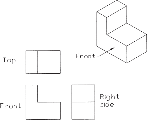
Drafting- drawings done by technical men and skilled industrial workers which are also freehand drawings but are shown in a special type of drawing called orthographic projection. Generally, an object is shown in three orthographic views—top, front, and side views.
2.After two dimensional drawings are done and all the shapes and sizes being laid-out, the next step to be executed to complete the process is_.
A. Dimensioning
B. Tolerancing
Answer: A. Dimensioning
Dimensioning- is the process of measuring the sizes of parts and overall sizes of assemblies are conveyed by dimensions placed on the drawing.
Tolerancing- is the process the total amount a dimension. may vary and is the difference between the upper (maximum) and lower (minimum) limits.
Specifications- drawing notes that describe materials, equipment, systems, standards, or workmanship are specifications
Sectional Drawing- shows a view of a structure as though it had been sliced in half or cut along another imaginary plane
3.With the help of drawing instruments such as T-square and triangles, one produces quick and accurate delineations for an intended project. The process is considered as:
A. Drafting
B. Pictorial Drawing
Answer: A. Drafting
Drafting- in drafting a draftsman in making drawings use mechanical drawing tools commonly used in mechanical drawings such as dividers, drawing boards, pencils, scales, triangles and t- squares.
Pictorial Drawing- view of an object (actual or imagined) as it would be seen by an observer who looks at the object either in a chosen direction or from a selected point of view.
Graphics- is the making of architectural or design drawings.
Shape and Size Descriptions- is the shapes of all the parts and their interrelation are exactly described by the representation of that information in the set of drawings
4. Technical drafting involves the manipulation of the elements of geometry to make accurate description of shapes. Which term is referred to by engineering’s and drafting professionals all over world?
A. Blueprint Reading
B. Geometric Construction
Answer: B. Geometric Construction
Geometric Construction- refers to the process of drawing lines, angles, and other geometric shapes and figures using only a compass and a straightedge
Blueprint Reading- are 2-dimensional architectural design drawings that indicate the size of a planned building,
Line Weight- is the light or darkness and width of a line.
Measurement- the process of associating numbers with physical quantities and phenomena.
5. Objects to be drawn are not always solid in nature and if we want to explain complex objects to the reader of our blueprints we need an imaginary cut through the component or an assembly drawing to portray exactly what is inside. This element is called:
A. Sectioning
D. Dimensioning
Answer: A. Sectioning
Sectioning- the process of sketching the internal configuration of an object by showing it cut apart is known as sectioning. Sectioning is used frequently on a wide variety of Industrial drawings.
Parallel Perspective- linear perspective in which parallel lines of the object that are perpendicular to the drawing surface are represented as meeting at a point on the horizon in line with the common point of intersection of the lines of projection— called also one-point perspective.
Etching- is an intaglio printmaking process in which lines or areas are incised using acid into a metal plate in order to hold the ink.
Dimensioning- the process of adding size information to a drawing is known as dimensioning the drawing.
6. To make drawings look more professional, the notes, dimensions, and other specifications must be professionally executed. In manual drafting this is called:
A. Lettering by the hand
B. Scaling
Answer: A. Lettering by the hand
Lettering by the hand- is the process of forming letters, numerals, and other characters in technical drawing. It is used to describe, or provide detailed specifications for, an object. With the goals of legibility and uniformity, styles are standardized and lettering ability has little relationship to normal writing ability.
Scaling- is a drawing method used to enlarge or reduce a drawing in size while keeping the proportions of the drawing the same.
Drawing of views- basically drawing of different views, Front, Rear, Side View
Legibility- is mostly a function of typeface design. It's a measure of how easy it is to recognize one letter or word from another and how easy blocks of text are to read. | the quality of being clear enough to read..
7. In various engineering fields, multiple line weights are being to emphasize areas of drawing. It is also standardized in order for a uniform interpretation drawing. The term is called:
C. Alphabet lines
D. Dimensioning
Answer: C. Alphabet of lines
Alphabet of lines- use of line symbols enables engineers/designers to express the features of designed products clearly and accurately. Line features vary not only by width but also by how they are graphically represented in a drawing.
Horizontal Line- is a straight line that is drawn from left to right or right to left and it is parallel to the x-axis in the coordinate plane.
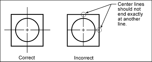
Center line- a real or imaginary line that is equidistant from the surface or sides of something.
Dimensioning- the process of adding size information to a drawing is known as dimensioning the drawing.
8.It is about placing units of measure to the height, width, and length of an object to convey accurate instructions to part. In old English it is called “dimensions”. In drafting this means:
B. Datum
D. Dimensioning
Answer: D. Dimensioning
Dimensioning- the process of adding size information to a drawing is known as dimensioning the drawing.
Tolerance- the difference between the acceptable maximum and minimum dimensions given for a hole, shaft, or other feature is known as the tolerance.
Datum- is a plane, a straight line, or a point that is used as a reference when processing a material or measuring the dimensions of a target.
Axis- is a line that runs straight through something in order to show the direction and movement of something.
9. Which is a method of representing the exact shape and size of an object drawn to scale on “set of planes” which sometimes are called planes of projection? It is also known as 3-view drawing.
A. Orthographic Projection
Answer: A. Orthographic Projection
Orthographic Projection- drawings occur in multi-drawing sets in order to depict each side, top and bottom view. Professions in design and construction use these types of drawings to inform the viewer of layout, size and shape. House floor plans illustrate a common type of orthographic drawing.
Perspective Construction- is a technique for depicting three-dimensional volumes and spatial relationships in two dimensions, as if from the view-point of an observer.
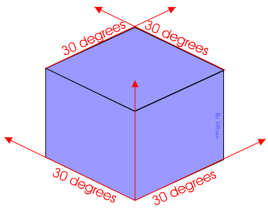
Isometric Drawing- a pictorial representation of an object in which all three dimensions are drawn at full scale rather than foreshortening them to the true projection. An isometric drawing looks like an isometric projection but all its lines parallel to the three major axes are measurable. 30 degree tilt.
Fourth Dimension- a dimension in addition to length, width, and depth, used so as to be able to employ geometrical language in discussing phenomena that depend on four variables: Time is considered a fourth dimension for locating points in space-time.
10. .Which technique in pictorial drawing appears like 3-dimensional but the lines are exactly 30 degrees from horizontal part of the object?
A. Isometric Drawing
C. Oblique Drawing
Answer: A. Isometric Drawing
Isometric Drawing- a pictorial representation of an object in which all three dimensions are drawn at full scale rather than foreshortening them to the true projection. An isometric drawing looks like an isometric projection but all its lines parallel to the three major axes are measurable. 30 degree tilt.
Cabinet Drawing- an oblique projection in mechanical drawing in which dimensions parallel to the third axis of the object are shortened one half to overcome apparent distortion.
Oblique Drawing- is a type of projective drawing in which the frontal lines are given in true proportions and relations and all others at suitable angles other than 90 degree without thinking about the rules of linear perspective.
Perspective Drawing- is what gives a three-dimensional feeling to a flat image such as a drawing or a painting. In art, it is a system of representing the way that objects appear to get smaller and closer together the farther away they are from the viewer.
11. I thing want is being ask here is most specifically used in drafting/ drawing that the most important part for the usefulness of the drawing it can be ruined if it is done carelessly:
B.Lettering
D.Calligraphy
Answer: B. Lettering
Lettering- is an umbrella term that covers the art of drawing letters, instead of simply writing them.
Painting- the practice of applying paint, pigment, color or other medium to a solid surface
Etching- is an intaglio printmaking process in which lines or areas are incised using acid into a metal plate in order to hold the ink.
Calligraphy- is the design and execution of lettering with a pen, ink brush, or other writing instrument.
12. Completing the adage “A good draft man will never letter without use of:
B.Guidelines
D.Border lines
Answer: B. Guidelines
Guidelines- a lightly marked line used as a guide, as in composing a drawing, a typed page, or a line of lettering. a rope or cord that serves to guide one's steps, especially over rocky terrain, through underground passages, etc.
Line- are used to direct an expression, in note form, to the intended place on the drawing.
Horizontal lines- is commonly used in technical analysis to mark areas of support or resistance.
Border lines- is a line drawn around the inside edge of the paper. Usually this is 10mmm from the edge of the paper.
13. Which of them are laid-out to touch the capital letter c aside from the base line. Where choices are parts of the guidelines indicated below.
A.Base line
D.Waist line
Answer: B. Cap line
Base line- the floor of the guideline
Cap line- the roof of the guideline
Drop line- line where "tails" of the letter lies
Waist line- middle part of the guideline

14. Which of these are positioned to limit letter g aside from waist line
A.Base line
C.Drop line
Answer: C. Drop line
Base line- the floor of the guideline
Cap line- the roof of the guideline
Drop line- line where "tails" of the letter lies
Waist line- middle part of the guideline
15. Of the many styles of letters, the most commonly used are script or italics, gothic, old English and roman. Which of them is most commonly used in college diploma?
A.Roman
C.Old English
Answer: C. Old English
Old English- common uses for Old English fonts include newspaper mastheads, legal publications and qualification certificates.
Roman- are overwhelmingly used in publications with long text passages, such as newspapers, magazines, and books.
Script or Italics- are widely used for invitations, branding, poster designs, advertising, display.
Gothic- it is best used for decorative purposes.
16. Time is gold so a drafter must not get into a habit of making excessively time-consuming letters. Single-stroke letters are advised with:
A.Rapidity of stroke
D.Free and natural
Answer: D. Free and natural
Rapidity of stroke- the phase or speed of the stroke
Sloppiness- the curve of strokes
Laziness- the quality of being unwilling to work or use energy
Free and natural- drawn or executed by hand without guiding instruments, measurements, or other aids. a freehand map
17. A grade 9 student understood that the Roman letters consist of thick and thin lines and was asking to him. What were those small thin lines at the end of every letter except O? in the drafting field the lines are called:
A.Serifs
B.Stem
Answer: A. Serifs
Serifs- is a decorative stroke that finishes off the end of a letters stem
Stem- are the main body of the letter
Dash line- use dashes to represent any line of an object that is hidden from view
Ditto- means 'again' or 'duplicate'
18.Prior to the introduction of Computer Aided Design and Drafting there are tools in lettering which are made of either plastic or aluminum on which the drafter just traced the letters using a technical pen to produce each letter. The instrument is called:
B.Lettering box
C.Leroy guide
Answer: B. Lettering box
Lettering box- set of tools use for lettering
Lettering template- are stencils that allows you to draw specific symbols and shapes that you use repeatedly in a design.
Leroy guide- was a popular mechanical lettering template used by professionals from the 1940s to the 1970s.
Pressure sensitive guide- refers to how your graphics tablet decides how thick or thin the lines you draw are, based on how much force you put down on your stylus.
19.For beginning drafters the suggested height of letters to practice first is 6mm and then shift to a height of:
A.30mm
B.3mm
Answer: B. 3mm
30mm- too narrow and too wide for begginenrs
3mm- fit for pracing
1mm- too narrow
50mm- too wide
20. In the field of Drafting, each line has a specific meaning. This is to establish a uniform way when interpreting complex blueprints of objects and other mega projects. These lines are called:
A.Alphabet of Lines
C.Language of Lines
Answer: A. Alphabet of Lines
Alphabet of Lines - are used to describe shape, size, hidden surfaces, interior detail, and alternate positions of parts. Each conveys a particular meaning on the drawing.. https://schoolworkhelper.net/technical-drawing-alphabet-of-line/
Alpha numeric of Lines- alphanumeric characters are a combination of alphabetical and numerical characters.
Language of Lines- there is no such
Lines of Sight-
21.Based on the Blueprint, machinist is about to drill a 16mm diameter hole on a piece of 100mmx120mm flat bar. Which line in the alphabet of lines must he look for first?
A. Hidden Line
C. Center Line
Answer: C. Center Line
Hidden Line- also known as a hidden object line is a medium weight line, made of short dashes about 1/8” long with 1/16”gaps, to show edges, surfaces and corners which cannot be seen.
Phantom Line- are long-short-short-long lines most often used to show the travel or movement of an object or a part in alternate positions.
Center Line- denote a circular feature such as a shaft or a hole. A rectangular feature seen on an elevation of a drawing could be identified either as a circular feature or a rectangular feature.
Section Line- show the kind of material from which the part is to be constructed. The material may not be indicated symbolically when its exact specification must also be shown elsewhere on the drawing.
22.When drawing the different views in orthographic projection, a drafter must acknowledge that there are hidden edges that must be emphasized in order to produce complete drawing information. Which line is he going to use?
A. Hidden Line
B. Section Line
Answer: A. Hidden Line
Hidden Line- are used to show surfaces that are not directly visible. All surfaces must be shown in all views. If an edge or surface is blocked from view by another feature, it is drawn using a hidden line.
Section Line- also known as a hidden object line is a medium weight line, made of short dashes about 1/8” long with 1/16”gaps, to show edges, surfaces and corners which cannot be seen.
Center Line- denote a circular feature such as a shaft or a hole. A rectangular feature seen on an elevation of a drawing could be identified either as a circular feature or a rectangular feature.
Object Line- thick, solid lines show the visible edges, corners, and surfaces of a part.
23.A drawing teacher on a local high school was discussing a feature on which the surface appears to have imaginary cut along the cutting plane line. Which line is she going to apply to the surface where the cutting plane cut through?
C. Section line
D. Invisible Line
Answer: C. Section line
Center Line- denote a circular feature such as a shaft or a hole. A rectangular feature seen on an elevation of a drawing could be identified either as a circular feature or a rectangular feature.
Dimension Line- line is a fine, dark, solid line with arrowheads on each end. It indicates direction and extent of a dimension
Section line- lso known as a hidden object line is a medium weight line, made of short dashes about 1/8” long with 1/16”gaps, to show edges, surfaces and corners which cannot be seen.
Invisible Line- are used to show surfaces that are not directly visible. All surfaces must be shown in all views. If an edge or surface is blocked from view by another feature, it is drawn using a hidden line.
24.There are six principal views of an object, TV, FV and RSV, RV, LSV, BV. Which the views are accepted by the industry as standard multi-views according to the 3rd angle projection?
A. Top view, front view, and right side view
C. Right side view, left side view, and bottom view
Answer: A. Top view, front view, and right side view
25.A group of students is experimenting on views in orthographic projection. They extract first the front view of a simple object using a transparent material as discussed by their teacher. What technique are they using?
A. Glass box technique
B. Onion skin technique
Answer: A. Glass box technique
Glass box technique- the image of the object is projected on the sides of the box. The box is unfolded. The sides of the box are the principal views.
Onion skin technique- is used to preview the previous and subsequent drawings with a translucent mode.
Japanese paper technique- These elegant Japanese art style is known as nihonga (Japanese painting) | Japanese paper cutting is called Kirie or Kirigami (literally meaning cut picture)
Polycarbonate technique- is a method that involves shape to a soft, flexible state, then fitting it around a custom mold
26.Orthographic projection goes farther than right angle. A drafter can actually extract views for more details of the object provided that the projectors are parallel to each other and normal to the plane of projection. The additional plane is called:
A. Frontal plane
B. Auxiliary plane
Answer: B. Auxiliary plane
Frontal plane - is the plane onto which the Front View (FV) of the multi-view drawing is projected. Front view of an object shows the width and height dimensions. Horizontal plane of projection is the plane onto which the Top View of the multi-view drawing is projected.
Auxiliary plane- a type of orthographic projection used to determine the true size and shape of inclined and oblique surfaces of objects
Profile plane- plane is vertical in position, and may be used as a plane of projection. A projection on the profile plane is called a profile view, or end view, or sometimes edge view,
Horizontal plane- is the plane onto which the Top View of the multi-view drawing is projected
27.All of objects have distinct limits which can be considered as the width, depth, and height. So when a drafter is working on the difference in elevation between any two points, measured as the perpendicular distance between a pair of horizontal lines, he is now engaged in the_ of the object?
A. Depth
C. Width
Answer: C. Width
Depth- is measured at the middle of the length, from the top of the keel to the top of the deck beam at the side of the uppermost continuous deck.
Height- he measurement from base to top
Width- the measurement or extent of something from side to side.
Bottom- the lowest point or part of something.

28.When an engineer is engaged in the preparation of views prior to formal drafting activities, he practically bases his information on actual and accurate observation. This process is regarded as:
A. Pencil and paper exercise
C. Orthographic sketch
Answer: C. Orthographic sketch
Pencil and paper exercise-
Glass box technique- the image of the object is projected on the sides of the box. The box is unfolded. The sides of the box are the principal views.
Orthographic sketch- common method of representing three-dimensional objects, usually by three two-dimensional drawings in each of which the object is viewed along parallel lines that are perpendicular to the plane of the drawing.
Order drawing- property settings specify in which order the markers for the selected column should be drawn.
29.After all the views are given, the drafter must now work on the real form of the objects based on actual result of the orthographic projection. This process is called:
A. Pictorial drawing
B. Depth dimensioning
Answer: A. Pictorial drawing
Pictorial drawing- A view of an object (actual or imagined) as it would be seen by an observer who looks at the object either in a chosen direction or from a selected point of view. Pictorial sketches often are more readily made and more clearly understood than are front, top, and side views of an object.
Depth dimensioning- process of putting the dimenson for depth
Height dimensioning - process of putting the dimenson for height
Center dimensioning- process of putting the dimenson for center location on the object
30 In isometric drawings, the angle used to aid the construction of the object is 30 degrees and all vertical line are equal lengths or scale but in oblique drawing the angle used is:
Answer: B. 45 degrees
45 degrees
30 degrees
31.In oblique drawing, the depth of the object is reduced to ½ in case of cabinet oblique, ¾ in case of a general oblique, and true or same measurement in _____ oblique.
B. Cavalier
C. Specific
Answer: B. Cavalier
Cavalier - actual measurement
Cabinet - size reduced to 1/2
General - size reduce to 1/4

'
32.Which technique is commonly used around the world as a graphic method or representing a 3- dimensional object and intended to combine the illusion of depth, with the undistorted presentation of the object’s principal dimension?
32.Which technique is commonly used around the world as a graphic method or representing a 3- dimensional object and intended to combine the illusion of depth, with the undistorted presentation of the object’s principal dimension?
A. Cavalier oblique
B. Isometric drawing
C. Cabinet oblique
D. General oblique
B. Isometric drawing
Answer: B. Isometric drawing
Cavalier oblique- redecing size is scaled from actual size
Isometric drawing- is a form of 3D drawing, which is set out using 30-degree angles. It is a type of axonometric drawing so the same scale is used for every axis, resulting in a non-distorted image.
Cabinet oblique- receding sisze is half of the actual size
General oblique- receding size is two thirds of actual size
A. Perspective drawing
B. Isometric drawing
Answer: A. Perspective drawing
Perspective drawing- is a technique to create the linear illusion of depth. As objects get further away from the viewer they appear to decrease in size at a constant rate. The box in the sketch below appears solid and three dimensional due to the use of perspective
Isometric drawing- is a form of 3D drawing, which is set out using 30-degree angles. It is a type of axonometric drawing so the same scale is used for every axis, resulting in a non-distorted image..
Diametric drawing- a way of drawing an object so that one axis has a different scale than the other two axis in the drawing. An example of dimetric projection is a technical drawing that shows a 3-dimensional cube with one side of the cube smaller in proportion to the other two sides.
Cabinet drawing- an oblique projection in mechanical drawing in which dimensions parallel to the third axis of the object are shortened one half to overcome apparent distortion.
34.A student in drafting has done three views; his next task is to indicate the dimensions to complete the information. What is the distance of the first dimension from the views?
Answer: B. 2”
Answer: B. 2”
1”
2”
35.There is a good reason why we should not place dimensions directly on the itself. This is to avoid?
B. Overcrowding of dimensions
D. Aligned dimension
Answer: D. Aligned dimension
Super dimensioning- there is no such
Overcrowding of dimensions- overused or repeated notes of dimension
Inaccurate dimensions- putting incorrect dimension
Aligned dimension- it is written in two directions in the whole drawing.
36.The radius of an arc should always be specified by the drafter in the form of a symbol which denotes_.
The radius of an arc should always be specified by the drafter in the form of a symbol which denotes_.
A. R
B. r
C. rad
D. ra
A. R
B. r
r- Radius of an arc or circle. The radius is represented by the lowercase letter r.
R- The letter 'R' as shown is used widely in drawings and is short for the word Radius.
rad- rapid application development
ra- roughness average;
37.It is important to the drafting students to place the overall dimension of a part or view to appear more pleasing to the reader. It is placed starting from the_.
Answer: A. Shortest dimension line outside the view
A. Shortest dimension line outside the view
B. Longest dimension line outside the views
C. Longer dimension inside the view
D. Shorter dimension inside the view
B. Longest dimension line outside the views
Should be on the outside, from shortest to lengest
38.Some drafter often place dimensions every while the maybe permitted in some drafting classes let us keep in mind that these are repetitions and can be avoided. This is referred to as_.
A. Superfluous dimension
B. Unidirectional dimensioning
C. Aligned dimensioning
D. Tolerance dimensioning
A. Superfluous dimension
C. Aligned dimensioning
Answer: A. Superfluous dimension
Superfluous dimension- dimensions that are repeated on the same view or on different views, or the same information be given in two different ways./ unnecessary dimensions
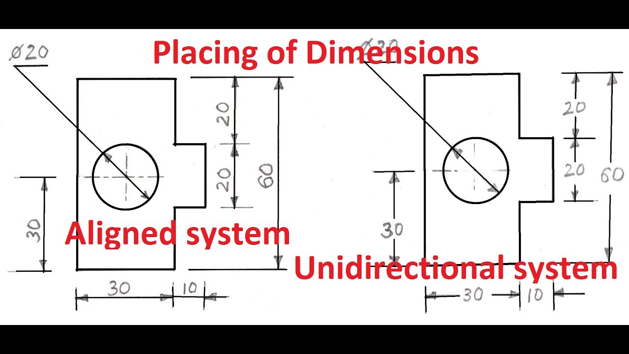
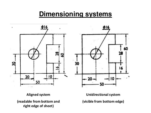
Unidirectional dimensioning- commonly used in drafting. dimensions are placed in such a way that they can be read from the bottom edge of the drawing sheet. Dimensions are inserts by breaking the dimension lines at the middle.
Aligned dimensioning- it is written in two directions in the whole drawing.
Tolerance dimensioning- There are essentially two methods of adding tolerances to dimensions firstly universal tolerancing and secondly specific tolerancing.

39.In the rule of sectional drawing, all visible edges exposed by the cutting-plane line must be emphasized and series of lines can now be drawn. This process is called_.
A. Filling-up of section lines
B. Eliminating hidden lines
C. Eliminating object lines
D. Symmetrical objects
B. Eliminating hidden lines
Answer: A. Filling-up of section lines
Filling-up of section lines- putting lines, or imaginary cut
Eliminating hidden lines- eliminating hidden lines
Eliminating object lines- removal of dark lines or the object lines
Symmetrical objects- objects with equal sizes
Eliminating hidden lines- eliminating hidden lines
Eliminating object lines- removal of dark lines or the object lines
Symmetrical objects- objects with equal sizes
40.There are situations in executing sectional drawings that every drafter must be familiar with especially when dealing with blow-up part of an object. We find this very reasonable with tiny and complicated parts.
This refers to_.
This refers to_.
A. Detail sections or spot details
B. Dual dimensioning
C. Aligned objects
D. Isometric objects
B. Dual dimensioning
C. Aligned objects
D. Isometric objects
Answer: A. Detail sections or spot details
41.For a professional looking section detail, which additional feature shall a drafter include to really portray the drawing?
A.Line symbols
B.Common section line symbols for materials
Answer: B. Common section line symbols for materials
Line symbols- another term for alphabet of lines-
Common section line symbols for materials- the general purpose section lining symbol is used to represent any material
Material line weight- is the visual lightness, darkness, or heaviness of a line within a drawin
Symmetric object line- is a line that cuts a shape exactly in half. g.
Common Section line symbols for materials:

42.There are several types of section- a full section which the cutting plane line passes across entire object and half section on which the cutting plane passes through an object which is_.
A.Symmetrical
D.Common section
Answer: A. Symmetrical
Symmetrical- has identical parts mirroring each other across a line of symmetry
Orthographic- is a way of representing a 3D object by using several 2D views of the object.
Offset drawing- including in a single section several features of an object that are not in a straight line.
Common section- is used to represent any material
43.When a section is to be detailed according to the intended parts, assembly is called_.
A.Assembly of parts
C.Assembly of materials
Answer: A. Assembly of parts
Assembly of parts- is a presentation of a structure or product with its components connected together,in their relative working positions while in use.
Assembly section- there is no such, if so assume an object was sectioned and it's part as an assembly
Assembly of materials - there is no such
Assembly of common section- there is no such, if so assume an object had a common sections and it's part as an assembly
44.The world has adopted the metric system of dimensioning but some countries used it voluntarily depending on the situation they practice. What is the name of their approach?
B.Dual dimensioning system
C.Aligned system
Answer: B. Dual dimensioning system
Unidirectional system- dimensions are placed in such a way that they can be read from the bottom edge of the drawing sheet.
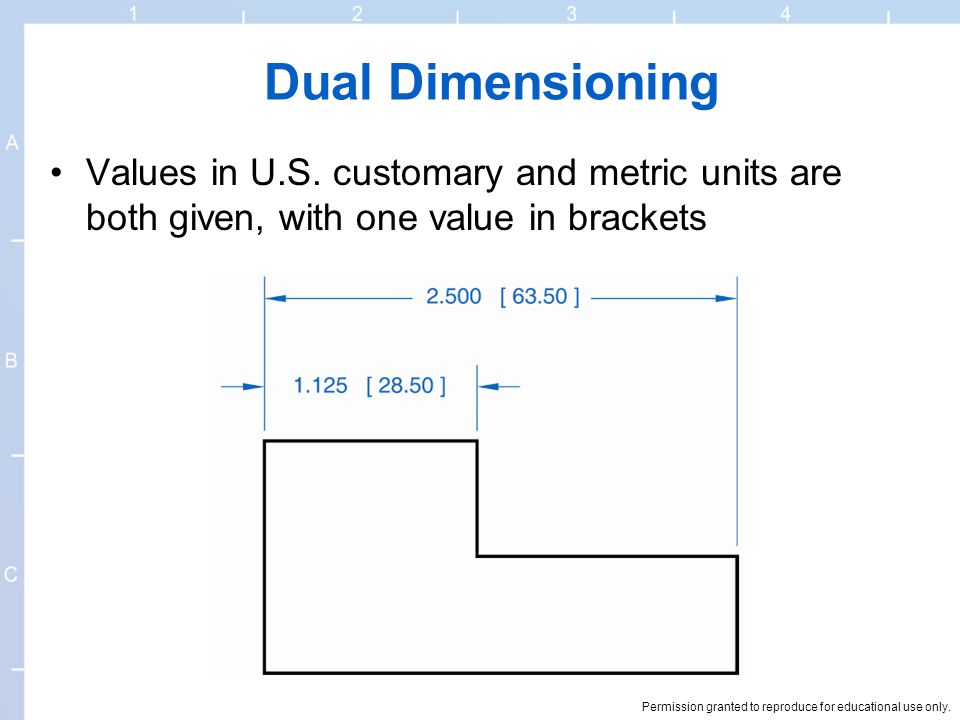
Dual dimensioning system- both metric and English measurements on a drawing. defines the size or geometric characteristic of a feature.
Aligned system- are placed above the dimension lines which are drawn without any break and written parallel to them
Position dimensioning- there is no such
45.A third-world country even for its stage can’t neglect drafting as part of its industrial pursuit is it manual, mechanized, or automated. So a citizen of a third world country must have the necessary skill in the use of:
A.Graphic or drafting language
B.Foreign language
Answer: A. Graphic or drafting language
Graphic or drafting language- in “engineering application” use lines to represent the surfaces, edges and contours of objects. A drawing can be done using freehand, instruments or computer methods. Composition of Graphic Language The language is known as “drawing” or “drafting” .
Foreign language
Sign language
English language
46.Mr. John cross purchased a 12.00m x 9.00m (frontal) land along the road. Local building code mandated that the building must have a set-back of 3.00m with respect to the edge of the paved barangay road. What then is the total area of the land minus the building code?
A.80 square meters
B.81 square meters
Answer: B. 81 square meters
Area for rectangle is A=lw
A=(12m-3m)9m
A= 81m^2 or 81square meter
47.Grade 10 students from a local central school in the North wanted to build a square culvert with one side open for an irrigation system. The dimensions are; w=80, d=1.20, h =.80m, and the thickness is .80m. What then is the set of drawings they need before giving it to an engineer to determine the size of reinforcement bars?
A.Top view, front view, right side view, isometric
B.Top view, front view, bottom view, isometric
Answer: A. Top view, front view, right side view, isometric
48.A half-moon protractor is divided into how many degrees?
B.180
D.310
Answer: B. 180

49.A line drawn with a long section, short dash, and another long section is a_.
C.Center axis of a hidden cylinder
D.Center of a radius
Answer: C. Center axis of a hidden cylinder
Hidden feature- represent the edges where surfaces meet but are not directly visible.
Center of a circle- indicate a circular feature on a drawing
Center axis of a hidden cylinder- line drawn with a long section, short dash, and another long section
Center of radius- a there ie no such
Center circle line

50.Traditional drafters need to be able to create several different line widths because_.
A.Different line widths convey different information
B.The line width has to with how dark it appear in the finished drawing
Answer: A. Different line widths convey different information
Different line widths convey different information
The line width has to with how dark it appear in the finished drawing
They seem to transmit better in a fax machine
It makes no difference
51.Several of the tools used in traditional drafting include the following:
A. Parallel straight edge
B. 45 degrees triangle
C. Circle template
D. All the above
Answer: D. All the above

52.A civil engineer working on a bridge design would probably rely on his _ scale for checking printed drawings.
A. Engineer’s
C. Architect’s
Answer: A. Engineer’s
Engineer’s Scale- The relation between the dimension on the drawing and the actual dimension of the object is mentioned numerically (like 10 mm = 15 m). • Graphical Scale: Scale is drawn on the drawing itself.
Metric Scale- are usually based on ratios. A ratio is the relationship of one measurement to another. For example, metric plot plans are often drafted in ratios of 1:100. This scale is very close to the scale 1/8" = 1'-0" (1:96).
Architect’s Scale- such as 1/4˝ = 1´-0˝ (1/48 size) or 1/8˝ = 1´-0˝ (1/96 size), are used for structures and buildings. They are used to measure interior and exterior dimensions such as rooms, walls, doors, windows, and fire protection system details. Other scale tools include flat scales and rolling scales.
None of the above
This item's explanation was limited to author's knowledge and research, thus incomplete. If you have any insights and correction kindly comment it below. It will surely be helpful on our future use.
53.In order to connect fractional inches into decimal inches_____.
A. Look on a metric conversion chart
B. Divide the numerator by the denominator
C. Check the engineer’s scale
D. All of the above
Answer: B. Divide the numerator by the denominator
Look on a metric conversion chart
Divide the numerator by the denominator
Check the engineer’s scale
All of the above
This item's explanation was limited to author's knowledge and research, thus incomplete. If you have any insights and correction kindly comment it below. It will surely be helpful on our future use.
54.An engineer would be used to measure lines on a drawing where the scale factor reads _____.
A. ¼” = 1’ – 0”
B. 1/8” = 1’ =0”
C. 1” = 100’
D. ¾”= 1’ 0”
Answer: C.1” = 100’
¼” = 1’ – 0”
1/8” = 1’ =0”
1” = 100’
¾”= 1’ 0”
This item's explanation was limited to author's knowledge and research, thus incomplete. If you have any insights and correction kindly comment it below. It will surely be helpful on our future use.
55.Referring to the fractional inches to decimal inches to millimeter conversion chart on page 55 what is the equivalent mm measurement of 3/16 inch?
A. 1.906
B. 4.7625
C. 5.958
D. 14.6844
Answer: B. 4.7625

This item's explanation was limited to author's knowledge and research, thus incomplete. If you have any insights and correction kindly comment it below. It will surely be helpful on our future use.
56.Some traditional board drafter preferred the drafting machine over the parallel straight edge because it could be used without the need for _____.
B. Triangles
D. Lettering guides
Answer: B. Triangles
57.The first step in creating a traditional technical drawing is to;_______
A. Draw a series of guidelines
C. Align the paper so that it will be positioned square to the parallel bar
Answer: C. Align the paper so that it will be positioned square to the parallel bar
This item's explanation is limited to author's knowledge and research, thus incomplete. If you have any insights and correction kindly comment it below. It will surely be helpful on our future use.
58.When lettering a CAD drawing, for clarity you should limit the number of fonts to:
A. One
B. Two
C. Three
D. Any number
Answer: B. Two
This item's explanation was limited to author's knowledge and research, thus incomplete. If you have any insights and correction kindly comment it below. It will surely be helpful on our future use.
59.The primary unit of measurement for engineering drawings and design in the mechanical industries is the:
A. millimeter
B. centimeter
Answer: A. millimeter
60.These units are based on inch-foot and yard measurements:
C. U.S. customary units
D. ISO international units
Answer: C. U.S. customary units
international customary units- the seven base units were chosen for historical reasons, and were, by convention, regarded as dimensionally independent: the metre, the kilogram, the second, the ampere, the kelvin, the mole, and the candela.
U.S. metric units- the metric system is a system of measurement that uses the meter, liter, and gram as base units of length (distance), capacity (volume), and weight (mass) respectively.
U.S. customary units-measure length and distances in the customary system are inches, feet, yards, and miles.
ISO international units- a coherent system of units of measurement starting with seven base units, which are the second (symbol s, the unit of time), metre (m, length), kilogram (kg, mass), ampere (A, electric current), kelvin (K, thermodynamic temperature), mole (mol, amount of substance), and candela (cd, luminous intensity)
61.This is how axonometric, oblique, and perspective sketches show objects:
A.Orthographically
B.Pictorially
Answer: B. Pictorially
| There are three (3) types of pictorial drawing; these are the Axonometric, Oblique, and Perspective drawings. The axonometric drawing is based upon the rotation principles; these are further classified into three (3) kinds, these are Isometric, Diametric and Trimetric. The Isometric shows the axis of revolution perpendicular to the horizontal plane. In here, the drawing or the object projects or shows two faces; the objects front as well as the view in the right side. The Diametric shows or projects two faces of views; the objects' top view as well as its left side view. The Trimetric shows or projects three faces or angles; the top view, the left and the right side view. In the Oblique drawing, one face of the object is parallel in the plane of projection. Like the isometric drawing, the Oblique drawing also uses three axes. The two of these axes are placed in perpendicular to each; while the third axis is placed in any angle that is convenient to the horizontal. There are two (2) types of Oblique drawing; these are the Cavalier drawing and the Cabinet drawing. In the Cavalier drawing, the receding lines usually are at thirty (30) degrees or it is at forty five (45) degrees to the horizontal axis. In the Cabinet drawing, the object is presented as it appears to a particular position in where the observer positioned relative to the object. This drawing presentation looks like the objects actually appear to the eyes of the viewer. The Perspective Drawing represents the objects as it would actually appear to the observer from a particular place. This is also another kind of pictorial drawing in which objects are presented as they actually appear to the viewers eyes. There are different kinds of pictorial drawing; the Parallel or One-Point Perspective, the Angular or Two Point Perspective and the Three Point Perspectives. 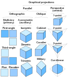 |
62.This type of projection is when projectors are parallel to each other, but are at an angle other than 90 degrees to the plane of projection:
A. Oblique projection
B. Perpendicular projection
Answer: A. Oblique projection
Oblique projection- a parallel projection in which the lines of sight are not perpendicular to the projection plane
Perpendicular projection- gives us a vector that is parallel to the vector whose length is how far the vector extends in the direction of
Aesthetic projection- there is no such
Angular projection- a pattern in which you insert, or project, the content you want to use inside another component.
63.There are two main types of projection:
B. Station-point and perspective
D. Perspective and parallel
Answer: B. Station-point and perspective
This item's explanation was limited to author's knowledge and research, thus incomplete. If you have any insights and correction kindly comment it below. It will surely be helpful on our future use.
64.The top, front, and bottom and views align in this manner.
A. Horizontally
B. Vertically
C. According to the planar views
D. Parallel to the frontal plane
Answer: B. Vertically
This item's explanation was limited to author's knowledge and research, thus incomplete. If you have any insights and correction kindly comment it below. It will surely be helpful on our future use.
65.If a plane is parallel to the plane of projection, it appears;
A. True size
B. As a line or edge
C. Foreshortened
D. As an oblique surface
Answer: A. True size
This item's explanation was limited to author's knowledge and research, thus incomplete. If you have any insights and correction kindly comment it below. It will surely be helpful on our future use.
66.This line pattern is composed of three dashes, one long dash on each end with a short dash in the middle:
A. Object
B. Hidden
C. Center
D. Phantom
Answer: C. Center
67.This is the plane upon which the top view is projected:
A. Horizontal
B. Frontal
C. Profile
D. Base
Answer: C. Profile
Front View- frontal plane
Side view - Horizontal Plane
Top View- Profile Plane
68.An advance of this type of view is that each view shows the object all the way through as if it were transparent.
A. Planar
B. Horizontal
C. Auxiliary
D. Orthographic
Answer: D. Orthographic
Planar- the portion of the object above the plane is omitted to reveal what lies beyond. In the case of a floor plan, the roof and upper part of the walls may be left out.
Horizontal- mostly the top view
Auxiliary- the plain where the orthograpic object is drawn
Orthographic- a way of representing a 3D object by using several 2D views of the object.
69.This type of surface is tipped to all principal planes of projection and does not appear true size in any standard view.
A.Foreshortened
B.Parallel
C.Orthographic
D.Oblique
Answer: D. Oblique
Foreshortened- is all about realistically conveying three dimensions in a 2D medium by showing objects moving away from the viewer.
Parallel- indicate ways in which two distinct things are similar
Orthographic- a way of representing a 3D object by using several 2D views of the object.
Oblique- have components such as cavalier, cabinet and military which sizes differs from original size.
70.Isometric drawings are often used by ______to help illustrate complex designs.
A.Mechanical engineers
B.Piping drafters
C.Aerospace engineers
D.All the above
Answer: D. All the above
Mechanical engineers- research, design, develop, build, and test mechanical and thermal sensors and devices, including tools, engines, and machines
Piping drafters- draft plans and drawings for the construction, operation, and layout of piping systems.
Aerospace engineers- evaluate designs to see that the products meet engineering principles.
All the above
71.A fillet is a rounded surface on the ___corner of a part.
A.Inside
B.Outside
Answer: A.Inside
A fillet or round connects two objects with a tangent arc in 2D, or creates a rounded transition between the adjacent faces of a 3D solid. An inside corner is called a fillet and an outside corner is called a round;

72.A round is a rounded surface on the ___corner of part.
A.Inside
B.Outside
Answer: B.Outside
A fillet or round connects two objects with a tangent arc in 2D, or creates a rounded transition between the adjacent faces of a 3D solid.
An inside corner is called a fillet and
An outside corner is called a round;

73.The bounding box method for setting up an isometric drawing helps the drafter____.
B.Figure what lines are to be illustrated vertical and horizontal
C.Position isometric drawing in paper space
Answer: B. Figure what lines are to be illustrated vertical and horizontal
First the drafter usually draw a solid cube and rectangular cube as the basis of the whole object.
74.The offset tool should only be used for placing_____ in an isometric drawing.
B.Horizontal lines
C.Vertical lines
Answer: C.Vertical lines
75.When creating an isometric drawing in Auto CAD, the drafter can utilize the Dynamic input and Polar Coordinate system to place both vertical and horizontal lines. A line created from one point 3 inches at 180 degrees would be a _____line.
A.Horizontal
B.Vertical
C.Inclined
D.None of the above
Answer: A.Horizontal
76.Auto CAD refers to isometric ellipses as ____
B.Isoellipses
C.Isocircle
Answer: C. Isocircle
Ellipsed- is a general command to create ellipse on the AutoCAD display
Isoellipsis- circles appear as ellipses and arcs as elliptical arcs
Isocircle- The Isocircle option of the ELLIPSE command allows you to easily construct isometric circles and arcs
Circle- is used to draw a circle by specifying the center point and radius.
77.These lines are used to indicate the measurement of objects and are represented by fine dark solid lines.
A.Leader lines
C.Dimensions lines
Answer: C. Dimensions lines
Leader lines- is a line that establishes a connection between a graphical representation of an item and some text. A leader points to a bit of our drawing and says: 'Oi – Look Here' and 'Read This! '
Extensions lines- continue or extend from the surface of the object and establish the size of the dimension.
Dimensions lines- indicate the measurements of objects in a drawing.
Center lines- are drawn to indicate the exact centre of a component being drawn.
78.If a drawing has an equal measure then it refers to __________.
B. Isometric drawing
C. Mechanical drawing
Answer: B. Isometric drawing
Perspective drawing -is a technique to create the linear illusion of depth. As objects get further away from the viewer they appear to decrease in size at a constant rate.
Isometric drawing- is a form of 3D drawing, which is set out using 30-degree angles. It is a type of axonometric drawing so the same scale is used for every axis, resulting in a non-distorted image.
Mechanical drawing- is a technique used to represent a three-dimensional object on a two-dimensional piece of drawing paper. Mechanical drawings are a series of two-dimensional views. They give an exact representation of the object and show all parts in their true size relation.
Oblique drawing- is a type of projective drawing in which the frontal lines are given in true proportions and relations
79.When parts that are not seen are represented by series of light dash lines then this line is classified as _________.
A.Reference line
D.Invisible line
Answer: D. Invisible line
Reference line-are multiple semi-transparent lines that are drawn in parallel to your axes and from your vanishing points, at an equal distance or angle from each other, to cover your entire drawing space with visual guides.
Visible line-are the edges or "outlines" of an object. They are drawn as solid lines with a thick/heavy weight.
Section line- are special lines placed on a drawing which indicate the area of the drawing through which an imaginary cut has been made to reveal internal details.
Invisible line- trace paths of motion across the visual field. Invisible lines are very powerful, yet may not affect everyone exactly the same way.
80.One of the best practices of a good draftsman is to NEVER letter without __________.
A.Guide lines
C.Lettering pens
Answer: A. Guide lines
Guide lines- a lightly marked line used as a guide, as in composing a drawing, a typed page, or a line of lettering.
Pencil-
Lettering pens
Ink-
81.If drawing has one surface that is parallel to the picture plane then this method is called ____.
A. Oblique drawing
B. Isometric drawing
Answer: A. Oblique drawing
Oblique drawing
Isometric drawing
Perspective drawing
Orthographic drawing

See that one of the side from the front view of the oblique drawing is parallel to the drawing plane. While orthographic will show 3 different views of the object.
82.This pictorial view is normally seen by the observer’s eyes. Which one is it?
A. Isometric drawing
C. Perspective drawing
Answer: C.Perspective drawing
Isometric drawing- is a form of 3D drawing, which is set out using 30-degree angles. It is a type of axonometric drawing so the same scale is used for every axis, resulting in a non-distorted image.
Oblique drawing-a projective drawing of which the frontal lines are given in true proportions and relations and all others at suitable angles other than 90 degrees without regard to the rules of linear perspective.
Perspective drawing- is a technique to create the linear illusion of depth. As objects get further away from the viewer they appear to decrease in size at a constant rate. The box in the sketch below appears solid and three dimensional due to the use of perspective.

Orthographic drawing- are also known as multiviews. The most commonly used views are top, front, and right side. You can imagine it as positioning yourself directly in front, above, or to the right of an object and drawing only what you can see. LINES
83.The line used to show clearly the dimension limits as called ____?
A. Center line
B. Extension line
Answer: B. Extension line
Center line- are drawn to indicate the exact centre of a component being drawn. They are made from a series of lighter long and short dashes.
Extension line- are fine, dark, solid lines that extend outward from a point on a drawing to which a dimension refers. Usually, the dimension line meets the extension line at right angles.
Dimension line-is a fine, dark, solid line with arrowheads on each end. It indicates direction and extent of a dimension.

Phantom line or section line-drawing which indicate the area of the drawing through which an imaginary cut has been made to reveal internal details. These lines are drawn at full density and should be drawn at certain dimensions.

84.A horizontal line used to determine the general height of lower case letters.
B. Cap line
C. Waist line
Answer: C.Waist line
Base line
Cap line
Waist line
Drop line
85.Letters that are composed of uniform width elements are classified as _____.
A. Italic letters
B. Text letters
C. Gothic letters
D. Roman letters
Answer: C.Gothic letters
Italic letters- are special lines placed on a is when a typeface is slanted to the right
TEXT letters- a large or capital letter.
Gothic letters- is a style of lettering that is popular as a font (or typeface) for artistic projects and
other uses. It is featured in many computer operating systems, and is a printing option in most print shops. Gothic lettering is a "sans serif" lettering style that is closely related to Germanic cultures.
Roman letters- the normal typography style in which the vertical lines of the characters are straight up and not on an angle
This item's explanation was limited to author's knowledge and research, thus incomplete. If you have any insights and correction kindly comment it below. It will surely be helpful on our future use.
86.Horizontal lines are best drawn using this instrument.
A. T-square
B. Ruler
Answer: A. T-square
T-square

Ruler

Meter stick

Triangles
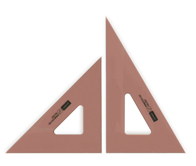
87.The drawing pencil of a draftsman is graded the softest, medium, and hardest. Which of the following grades is the softest?
A. 6B
B. HB
C. 3B
D. 9H
Answer: A. HB
-B stands for "black". These pencils are soft.
-H stands for "hard".
-HB stands for "hard black", which means "medium hard".
-F stands for "firm".
- The hardest of the drawing pencils is the 9H.
The next hardest in order are the 8H, 7h, 6H, 5H, 4H, 3H, 2H, H, HB, B, 2B, 3B, 4B, 5B, and 6B.
The 6B is the softest of all the drawing pencils. It is used mainly by artists for sketching.
Most work in engineering drawing is done with the 4H, 2H, and H pencils.
Generally the 4H pencil is used for layout for construction lines, the 2H pencil for general line work, and the H pencil for lettering.
88. Which grade of pencil is commonly used for lettering by a draftsman?
A. 2H
B. HB
C. 4H
D. 6H
Answer: B. 2H
- The hardest of the drawing pencils is the 9H.
The next hardest in order are the 8H, 7h, 6H, 5H, 4H, 3H, 2H, H, HB, B, 2B, 3B, 4B, 5B, and 6B.
The 6B is the softest of all the drawing pencils. It is used mainly by artists for sketching.
Most work in engineering drawing is done with the 4H, 2H, and H pencils.
Generally the 4H pencil is used for layout for construction lines, the 2H pencil for general line work, and the H pencil for lettering.
89.A drawing instrument that serves as guide in drawing vertical and diagonal lines as in triangles. It is generally used in drawing horizontal lines. Which one is it?
A. Triangular scale
B. T- square
Answer: B. T- square
Triangular scale
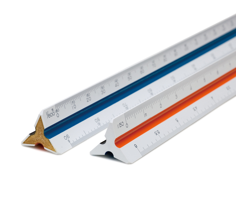
T- square
Triangle
French curve

90.Which is instrument is used in drawing curves except circles and arcs?
A. Compass
D. Divider- instrument for measuring, transferring, or marking off distances,
Answer: C. Divider
Compass
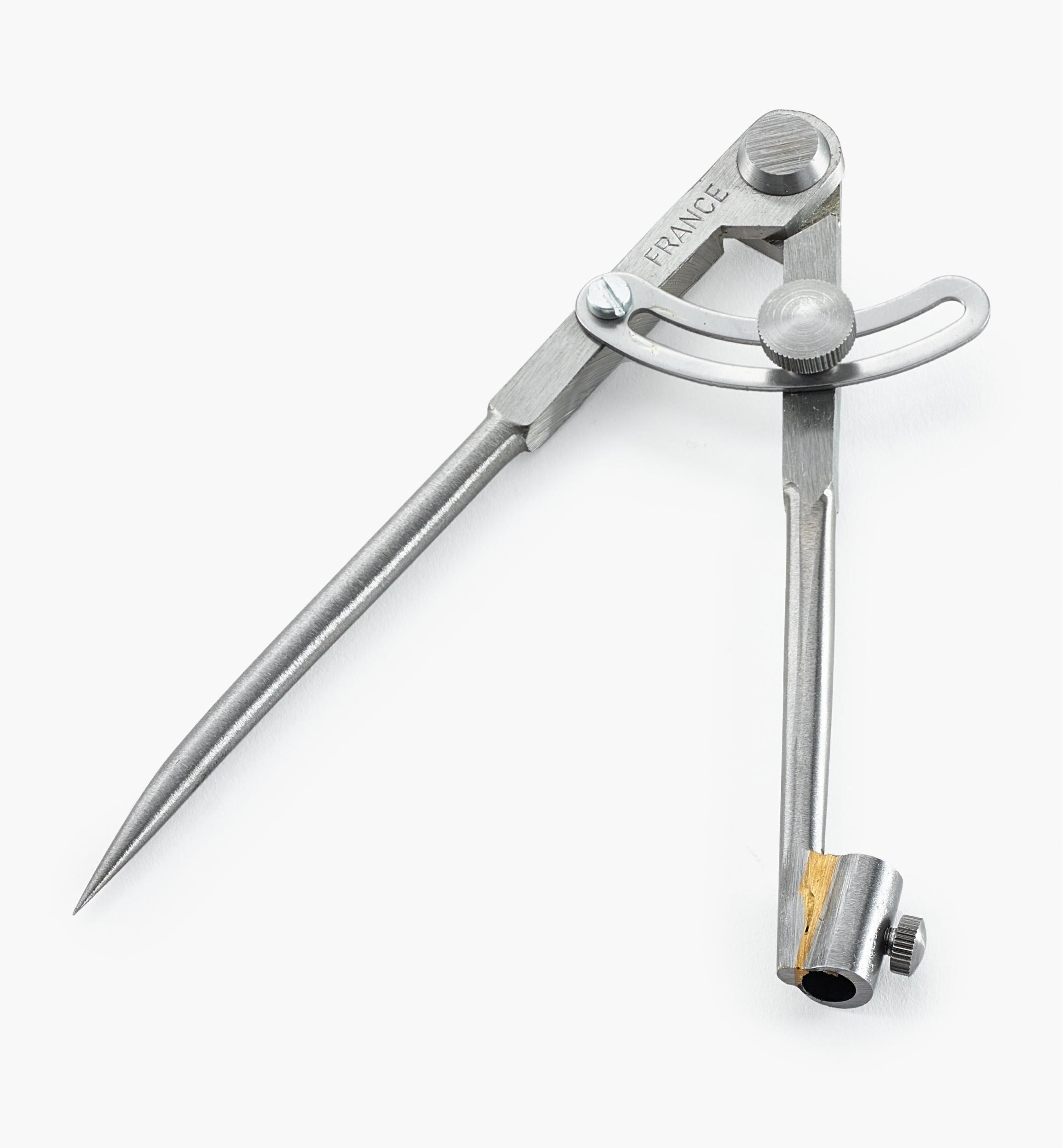
Protractor
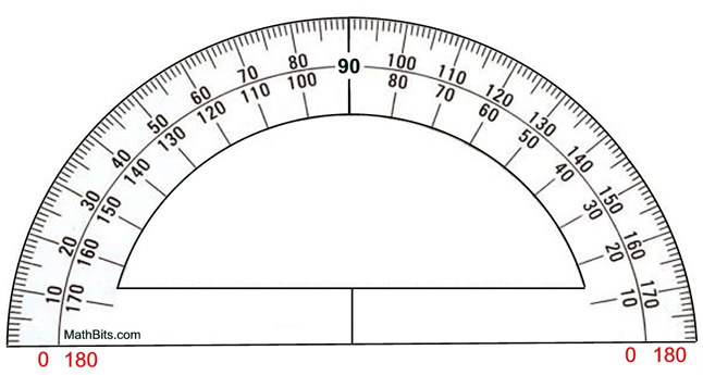
French curve
Divider

91.To completely describe a cone, sphere, and rectangular pyramid the number of views needed is ______.
B. Two
C. Three
Answer: B. Two

92.This line is projected as a shorter line in a drawing.
A. Incline line
B. Vertical line
Answer: A. Incline line
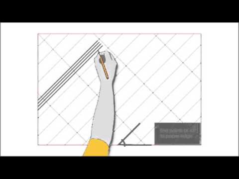
Incline line- a line which is oblique to the plane of the horizon.
This item's explanation is limited to author's knowledge and research, thus incomplete. If you have any insights and correction kindly comment it below. It will surely be helpful on our future use.
93.Boxing method is the most widely used method of drawing a/an _____.
A. Isometric view
B. Pictorial view
Answer: A. Isometric view
Since Isometric creates objects that was undistorted, box method is an ideal base of the drawimg.

94.Two intersecting lines which form right angles are called ____.
C. Perpendicular lines
D. Tangent lines
Answer: C. Perpendicular lines
Parallel lines- lines in a plane that are always the same distance apart.
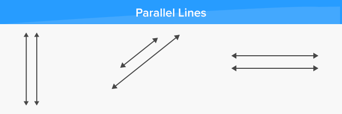
Perpendicular lines- lines are defined as two lines that meet or intersect each other at right angles (90°).

Tangent lines- is a line that just touches the graph of the function at the point in question and is “parallel” (in some way) to the graph at that point.
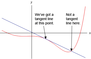
95.A polygon is classified according to the number of sides. What do you call a four – sided polygon?
A. Pentagon
B. Quadrilateral
Answer: B. Quadrilateral
Pentagon- 5 sides
Quadrilateral - 4 sides
Hexagonal- six sides
Octagon- eight sides
96.How many meters is thirty feet?
C. 12 meters
D. 9 meters
Answer: D. 9 meters
1 feet = 0.3048 m
30feet x 1 ft.
? 0.3048 m
=9.144 m
97.Drafting material used for fastening the drawing paper on the drawing table.
C. Masking tape
D. Triangle
Answer: C. Masking tape
Compass- more accurately known as a pair of compasses, is a technical drawing instrument that can be used for inscribing circles or arcs.

Divider- instrument for measuring, transferring, or marking off distances, consisting of two straight adjustable legs hinged together and ending in sharp points.
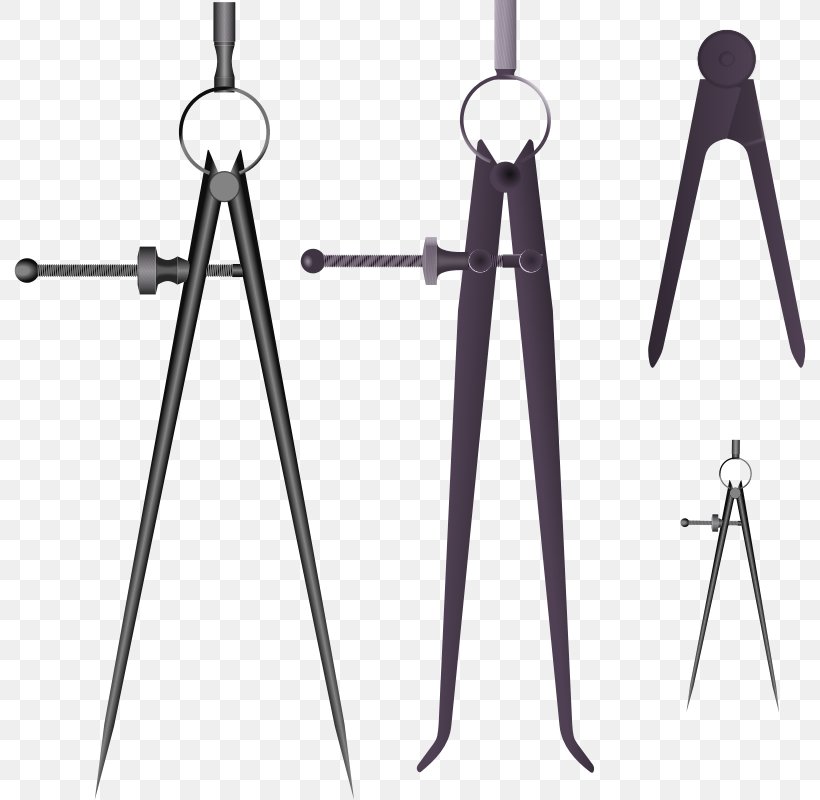
Masking tape- has a lower tack. It is intended to hold blueprints to a drawing board or light table, and to pull off easily without damaging the drawing.

Triangle- is a drafting tool used to draw accurate parallel lines, vertical lines, and other angled lines.

98.The main function of this tool is to reproduce the measurements of an object to any size.
A. Compass
B. Protractor
C. Triangles
D. Triangular scales
Answer: D. Triangular scales
Compass- more accurately known as a pair of compasses, is a technical drawing instrument that can be used for inscribing circles or arcs.
Protractor- is a tool used in drafting to draw and measure angles other than 30°, 45°, 60°, or 90°.
Triangles- is a drafting tool used to draw accurate parallel lines, vertical lines, and other angled lines.
Triangular scales- is a ruler that has a 3-lobed cross-section with 6 different types of scales on the edges (2 on each face) used for measuring and preparing scale drawings such as blueprints and maps. It is also called an architect's scale.
99.This drafting tool is used to protect the rest of drawing when removing unnecessary lines.
A. Erasing shield
C. Masking tape
Answer: A. Erasing shield
Erasing shield- is a thin sheet of stainless steel or plastic with slots and holes of different shapes. They are designed to allow erasers to be used through them to erase lines and text without removing lines close by which do not need to be (or should not be) erased.
100.Best tool when measuring arcs, angles, and circles.
C. Protractor
D. Divider
Answer: C. Protractor
Protractor- is a tool used in drafting to draw and measure angles other than 30°, 45°, 60°, or 90°.


Comments
Post a Comment