Prof. Ed., General Education, Drafting, Plumbing, Carpentry, Masonry, Entrepreneurship, Basic Elerctronics, Basic Electricity, Business Math, Cosmetology, Foods with Key Answers, Explanations, Notes, and Concepts
TLE: Drafting Part 3
Get link
Facebook
X
Pinterest
Email
Other Apps
21.Based on the Blueprint, machinist is about to drill a 16mm diameter hole on a piece of 100mmx120mm flat bar. Which line in the alphabet of lines must he look for first?
A. Hidden Line
B. Phantom Line
C. Center Line
D. Section Line
22.When drawing the different views in orthographic projection, a drafter must acknowledge that there are hidden edges that must be emphasized in order to produce complete drawing information. Which line is he going to use?
A. Hidden Line
B. Section Line
C. Center Line
D. Object Line
23.A drawing teacher on a local high school was discussing a feature on which the surface appears to have imaginary cut along the cutting plane line. Which line is she going to apply to the surface where the cutting plane cut through?
A. Center Line
B. Dimension Line
C. Section line
D. Invisible Line
24.There are six principal views of an object, TV, FV and RSV, RV, LSV, BV. Which the views are accepted by the industry as standard multi-views according to the 3rd angle projection?
A. Top view, front view, and right side view
B. Side view, bottom view, and rear view
C. Right side view, left side view, and bottom view
D. Front view, rear view and side view
25.A group of students is experimenting on views in orthographic projection. They extract first the front view of a simple object using a transparent material as discussed by their teacher. What technique are they using?
A. Glass box technique
B. Onion skin technique
C. Japanese paper technique
D. Polycarbonate technique
26.Orthographic projection goes farther than right angle. A drafter can actually extract views for more details of the object provided that the projectors are parallel to each other and normal to the plane of projection. The additional plane is called:
A. Frontal plane
B. Auxiliary plane
C. Profile plane
D. Horizontal plane
27.All of objects have distinct limits which can be considered as the width, depth, and height. So when a drafter is working on the difference in elevation between any two points, measured as the perpendicular distance between a pair of horizontal lines, he is now engaged in the_ of the object?
A. Depth
B. Height
C. Width
D. Bottom
28.When an engineer is engaged in the preparation of views prior to formal drafting activities, he practically bases his information on actual and accurate observation. This process is regarded as:
A. Pencil and paper exercise
B. Glass box technique
C. Orthographic sketch
D. Order drawing
29.After all the views are given, the drafter must now work on the real form of the objects based on actual result of the orthographic projection. This process is called:
A. Pictorial drawing
B. Depth dimensioning
C. Height dimensioning
D. Center dimensioning
30 In isometric drawings, the angle used to aid the construction of the object is 30 degrees and all vertical line are equal lengths or scale but in oblique drawing the angle used is:
A. 40 degrees
B. 45 degrees
C. 30 degrees
D. 60 degrees
Key Answers, Explanations, Notes, and Concepts
21.Based on the Blueprint, machinist is about to drill a 16mm diameter hole on a piece of 100mmx120mm flat bar. Which line in the alphabet of lines must he look for first?
A. Hidden Line
B. Phantom Line
C. Center Line
D. Section Line
Answer: C. Center Line
Hidden Line- also known as a hidden object line is a medium weight line, made of short dashes about 1/8” long with 1/16”gaps, to show edges, surfaces and corners which cannot be seen.
Phantom Line- are long-short-short-long lines most often used to show the travel or movement of an object or a part in alternate positions.
Center Line- denote a circular feature such as a shaft or a hole. A rectangular feature seen on an elevation of a drawing could be identified either as a circular feature or a rectangular feature.
Section Line- show the kind of material from which the part is to be constructed. The material may not be indicated symbolically when its exact specification must also be shown elsewhere on the drawing.
22.When drawing the different views in orthographic projection, a drafter must acknowledge that there are hidden edges that must be emphasized in order to produce complete drawing information. Which line is he going to use?
A. Hidden Line
B. Section Line
C. Center Line
D. Object Line
Answer: A. Hidden Line
Hidden Line- are used to show surfaces that are not directly visible. All surfaces must be shown in all views. If an edge or surface is blocked from view by another feature, it is drawn using a hidden line.
Section Line- also known as a hidden object line is a medium weight line, made of short dashes about 1/8” long with 1/16”gaps, to show edges, surfaces and corners which cannot be seen.
Center Line- denote a circular feature such as a shaft or a hole. A rectangular feature seen on an elevation of a drawing could be identified either as a circular feature or a rectangular feature.
Object Line- thick, solid lines show the visible edges, corners, and surfaces of a part.
23.A drawing teacher on a local high school was discussing a feature on which the surface appears to have imaginary cut along the cutting plane line. Which line is she going to apply to the surface where the cutting plane cut through?
A. Center Line
B. Dimension Line
C. Section line
D. Invisible Line
Answer: C. Section line
Center Line- denote a circular feature such as a shaft or a hole. A rectangular feature seen on an elevation of a drawing could be identified either as a circular feature or a rectangular feature.
Dimension Line- line is a fine, dark, solid line with arrowheads on each end. It indicates direction and extent of a dimension
Section line- lso known as a hidden object line is a medium weight line, made of short dashes about 1/8” long with 1/16”gaps, to show edges, surfaces and corners which cannot be seen.
Invisible Line- are used to show surfaces that are not directly visible. All surfaces must be shown in all views. If an edge or surface is blocked from view by another feature, it is drawn using a hidden line.
24.There are six principal views of an object, TV, FV and RSV, RV, LSV, BV. Which the views are accepted by the industry as standard multi-views according to the 3rd angle projection?
A. Top view, front view, and right side view
B. Side view, bottom view, and rear view
C. Right side view, left side view, and bottom view
D. Front view, rear view and side view
Answer: A. Top view, front view, and right side view
25.A group of students is experimenting on views in orthographic projection. They extract first the front view of a simple object using a transparent material as discussed by their teacher. What technique are they using?
A. Glass box technique
B. Onion skin technique
C. Japanese paper technique
D. Polycarbonate technique
Answer: A. Glass box technique
Glass box technique- the image of the object is projected on the sides of the box. The box is unfolded. The sides of the box are the principal views.
Onion skin technique- is used to preview the previous and subsequent drawings with a translucent mode.
Japanese paper technique- These elegant Japanese art style is known as nihonga (Japanese painting) | Japanese paper cutting is called Kirie or Kirigami (literally meaning cut picture)
Polycarbonate technique- is a method that involves shape to a soft, flexible state, then fitting it around a custom mold
26.Orthographic projection goes farther than right angle. A drafter can actually extract views for more details of the object provided that the projectors are parallel to each other and normal to the plane of projection. The additional plane is called:
A. Frontal plane
B. Auxiliary plane
C. Profile plane
D. Horizontal plane
Answer: B. Auxiliary plane
Frontal plane - is the plane onto which the Front View (FV) of the multi-view drawing is projected. Front view of an object shows the width and height dimensions. Horizontal plane of projection is the plane onto which the Top View of the multi-view drawing is projected.
Auxiliary plane- a type of orthographic projection used to determine the true size and shape of inclined and oblique surfaces of objects
Profile plane- plane is vertical in position, and may be used as a plane of projection. A projection on the profile plane is called a profile view, or end view, or sometimes edge view,
Horizontal plane- is the plane onto which the Top View of the multi-view drawing is projected
27.All of objects have distinct limits which can be considered as the width, depth, and height. So when a drafter is working on the difference in elevation between any two points, measured as the perpendicular distance between a pair of horizontal lines, he is now engaged in the_ of the object?
A. Depth
B. Height
C. Width
D. Bottom
Answer: C. Width
Depth- is measured at the middle of the length, from the top of the keel to the top of the deck beam at the side of the uppermost continuous deck.
Height- he measurement from base to top
Width- the measurement or extent of something from side to side.
Bottom- the lowest point or part of something.
28.When an engineer is engaged in the preparation of views prior to formal drafting activities, he practically bases his information on actual and accurate observation. This process is regarded as:
A. Pencil and paper exercise
B. Glass box technique
C. Orthographic sketch
D. Order drawing
Answer: C. Orthographic sketch
Pencil and paper exercise-
Glass box technique- the image of the object is projected on the sides of the box. The box is unfolded. The sides of the box are the principal views.
Orthographic sketch- common method of representing three-dimensional objects, usually by three two-dimensional drawings in each of which the object is viewed along parallel lines that are perpendicular to the plane of the drawing.
Order drawing- property settings specify in which order the markers for the selected column should be drawn.
29.After all the views are given, the drafter must now work on the real form of the objects based on actual result of the orthographic projection. This process is called:
A. Pictorial drawing
B. Depth dimensioning
C. Height dimensioning
D. Center dimensioning
Answer: C. Pictorial drawing
Pictorial drawing- A view of an object (actual or imagined) as it would be seen by an observer who looks at the object either in a chosen direction or from a selected point of view. Pictorial sketches often are more readily made and more clearly understood than are front, top, and side views of an object.
Depth dimensioning- process of putting the dimenson for depth
Height dimensioning - process of putting the dimenson for height
Center dimensioning- process of putting the dimenson for center location on the object
30 In isometric drawings, the angle used to aid the construction of the object is 30 degrees and all vertical line are equal lengths or scale but in oblique drawing the angle used is:
Answer: B. 45 degrees
40 degrees
45 degrees
30 degrees
60 degrees
Notes:
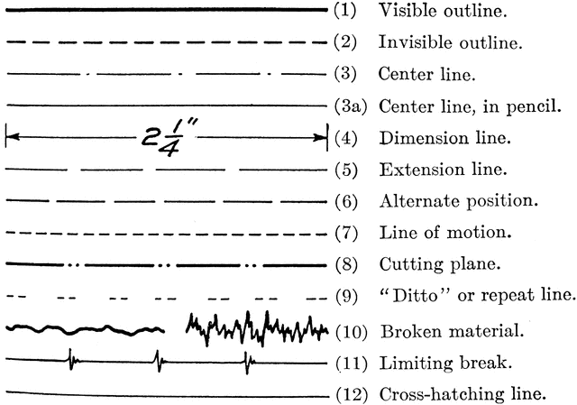
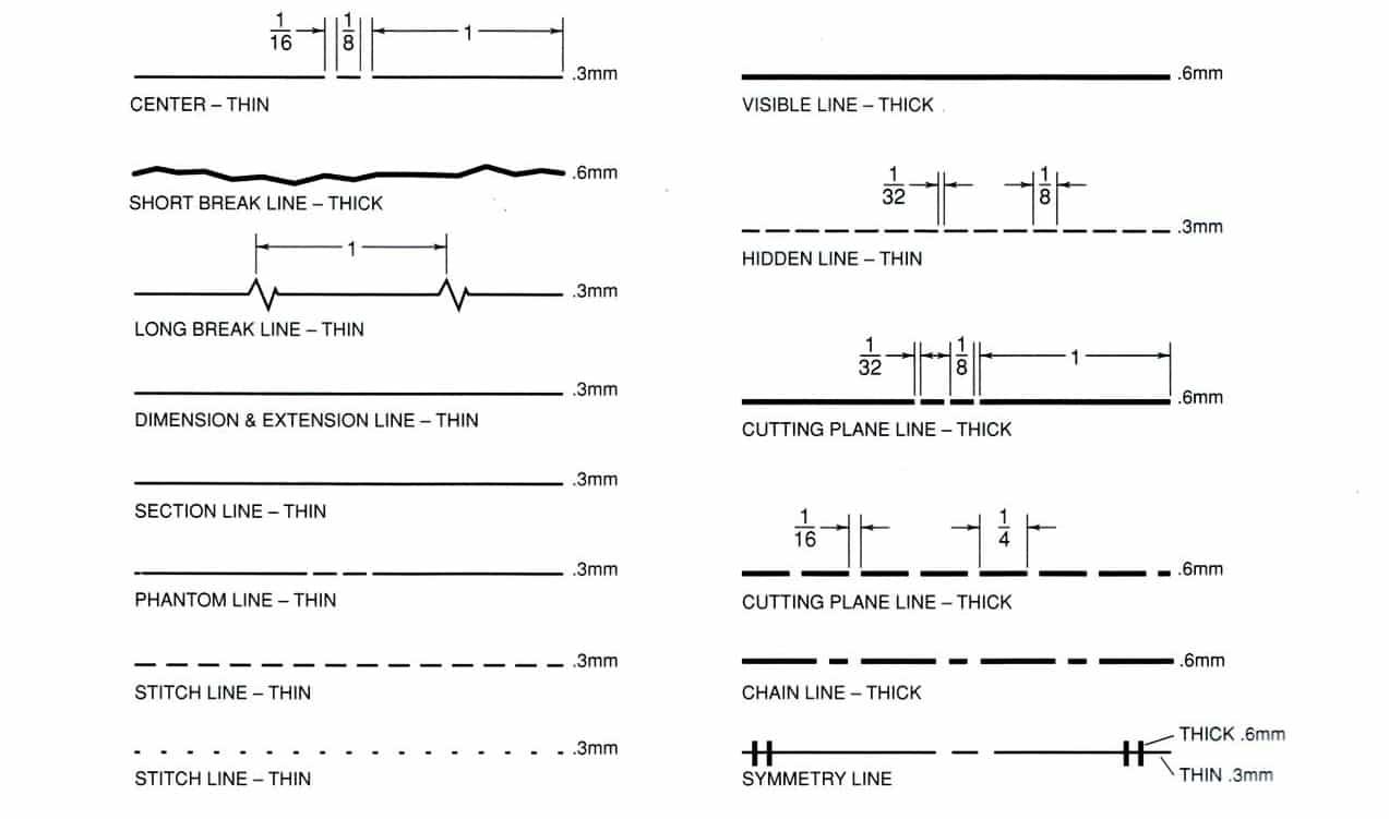
ALPHABET OF LINE
1. OBJECT OR VISIBLE LINES – Thick dark line use to show outline of object, visible edges and surfaces.
2. CONSTRUCTION LINE – Very light and thin line use to construct layout work.
3. DIMENSION LINE – Thin and dark lines use to show the size (span) of an object with a numeric value. Usually terminates with arrowheads or tick markings.
4. HIDDEN LINE – Short dash lines use to show non visible surfaces. Usually shows as medium thickness.
5. CENTER LINE – Long and short dash lines. Usually indicates center of holes, circles and arcs. Line is thin and dark.
6. EXTENSION LINE – Thin and dark line use to show the starting and ending of dimension.
7. CUTTING PLANE LINE – Extra thick lines use to show cutaway views or plane of projection where a section view is taken. Arrow indicates thedirection of view.
8. SHORT AND LONG BREAK LINES –Short and long medium line use to show cutaway view of a long section.
9. LEADER LINE – Medium line with arrowhead to show notes or label for size or special information about a feature.
10. PHANTOM LINE – Long line followed by two short dashes use to show alternate position of a moving part.
11. SECTION LINE – Medium lines drawn at 45 degrees use to show interior view of solid areas of cutting plane line.
SOME ADDITIONAL INFO GRAPHS
Comments, Suggestions and Corrections are highly appreciated. Kindly put those in the comments section. Fighting!
21) Which is considered to be the oldest and most commonly used building material? a. Cement b. Wood c. Steel d. Sand 22) A wood which is obtained from conifers and are used for framing? a. Hard wood b. Soft wood c. Dark wood d. Brown wood 23) Which wood is obtained from deciduous trees? a. Hard wood b. Soft wood c. Dark wood d. Brown wood 24) Which is a binding agent that reacts with water to form a hard stone-like substance? a. Glue b. Cement c. Mortar d. Grout 25) Which term refers to inert materials when bound together into a conglomerated mass from concrete? a. Aggregates b. Gravel c. Cement d. Water 26) A lumber that has been sawed, edged, and trimmed in which cutting marks are visible is ________. a. rough b. smooth c. dressed d. worked 27) Which lumber has been put through planing machine which gives fine surface? a. rough b. smooth c. dressed d. worked 28) Which lumber that has been dresses and matched, ship lapped, or patterned? a. rough b. smooth c. dressed d. worked 29) Whi...
Weekly Review. Sunday, 8:00-9:00 PM (GMT+8) Why are we doing this? Maybe you are thinking it's too early. Masyado pa namang maaga. Or why are we stressing ourselves while we can chill? This Weekly Review is to prepare us for the upcoming LET. Which consist of 450 items of exams. 150 for General education, 150 for Professional Education, and 150 for TLE or Majorship. Imagine na araw araw mong pinapraktis na magsagot ng exam, sa actual na LET kung saan isang buong araw mong it'take,maning mani nalang yung pagsagot dahil para sayo nasama na yan sa routine mo. Oo, pwede ka namang magreview center pagkagradute. Pero hindi ba pressure naman kung kaunting oras nalang yung meron ka para magreview? Iba parin yung may confidence ka. Iba parin yung ikaw mismo nag aral at nakadiscover ng mga sagot sa self review. Gaano ba kalaki ang 10...
81) Which refers to the ease with which the fresh concrete can be molded without segregation? a. Plasticity b. Consistency c. Mobility d. Grout 82) Which refers to the degree of wetness or slump of the concrete mixture? a. Plasticity b. Consistency c. Mobility d. Grout 83) Which is an artificial stone that results from mixing cement, sand, gravel, and water? a. Concrete b. Grout c. Mortar d. Bricks 84) Which is an artificial stone that results from mixing cement, sand, and water? a. Concrete b. Grout c. Mortar d. Bricks 85) Which is an artificial stone that results from mixing cement and water? a. Concrete b. Grout c. Mortar d. Bricks 86) Which term refers to the process of finishing using mortar? a. Finishing b. Fine finishing c. Concreting d. Plastering 87) A mason wants to lay ceramic tiles. Where does he start? a. Front b. Left c. Right d. Center 88) A mason wants to lay concrete hollow blocks. Where does he start? a. Front b. Left c. Right d. Center 89) A mason wants to mix mortar...
11) A schedule 40 pipe is: a. Thicker than schedule 20 b. Thicker than schedule 80 c. Thinner than schedule 10 d. None among the choices 12) What material is used to seal off threaded fittings to avoid leakage? a. Masking tape b. Teflon tape c. Scotch tape d. Adhesive gum 13) What must be installed to prevent siphonage or backflow of the water seal in the drainage system? a. Vent pipe b. Drain pipe c. Soil pipe d. Cleanout 14) Which of the following is NOT required by the National Plumbing Code? a. Drainage pipe should be inclined properly for a downward gravity flow of water. b. Drainage pipe should be provided with adequate cleanout. c. No vent pipe is needed. d. All pipe joints must be well-fitted and tightly connected. 15) What is the ideal inclination of a horizontal waste pipe as recommended by the National Plumbing Code? a. 2% slope b. 3% slope c. 4% slope d. 0% slope or level position 16) For purposes of troubleshooting in case of stoppage of flow, what must be installed in the...
31) The following are examples of plumbing fixtures, EXCEPT: a. water closet b. drainage c. shower d. urinals 32) Which statement is NOT true about plumbing standards based on Republic Act 1378 which is known as "Plumbing Law"? a. Each fixture directly connected to the drainage system shall be equipped with a water-sealed trap. b. Plumbing shall be designed and adjusted to use the maximum quantity of water consistent with proper performance and cleaning. c. Water closet must be located in a room which is properly lighted and ventilated. d. No substance which will clog the pipes, produce explosive mixtures, destroy the pipes or their joints or interfere unduly with the sewage disposal process shall be allowed to enter the building drainage system. 33) A compartment that receives solid or liquid waste, located below the normal grade of the gravity system is called ________. a. septic b. sump c. trap d. interceptor 34) Which is true toxic substance? a. Hazardous to human healt...
1.When a designer or an ordinary person translates his or her own design idea with the use of paper and pencil, what is the name of the activity? A. Architectural delineation B.Freehand Sketching C.Geometric Construction D.Drafting 2.After two dimensional drawings are done and all the shapes and sizes being laid-out, the next step to be executed to complete the process is_. A.Dimensioning B.Tolerancing C.Specifications D.Sectional Drawing 3.With the help of drawing instruments such as T-square and triangles, one produces quick and accurate delineations for an intended project. The process is considered as: A. Drafting B. Pictorial Drawing C. Graphics D. Shape and Size Descriptions 4.Technical drafting involves the manipulation of the elements of geometry to make accurate description of shapes. Which term is referred to by engineering’s and drafting professionals all over world? A. Blueprint Reading B. Geometric Construction C. Line Weight D. Measurement 5.Objects to be drawn are ...
Hi. I'm Franz. A third-year college student taking Bachelor of Technical Teacher Education Major in Automotive Technology at the time being. I am doing this blog for the purpose of reviewing myself for the Licensure Examination Test. You might tell that it's way too early for me to review. That is also why I want to take advantage of it. With no pressure, here is where I will post and review 10 questions daily. I will also compile notes, research, and explanations I've gathered. With my friends, we're also planning to have a weekly review in the future. Since you already have an access to this blog, I am hoping that you put this to good use. You can review this daily like how I do, read this in one go, or occasionally when you're on a bus or on your couch. This blog is still in the process. Questions and key answers ...
81.If drawing has one surface that is parallel to the picture plane then this method is called ____. A. Oblique drawing B. Isometric drawing C. Perspective drawing D. Orthographic drawing 82.This pictorial view is normally seen by the observer’s eyes. Which one is it? A. Isometric drawing B. Oblique drawing C. Perspective drawing D. Orthographic drawing 83.The line used to show clearly the dimension limits as called ____? A. Center line B. Extension line C. Dimension line D. Phantom line or section line 84.A horizontal line used to determine the general height of lower case letters. A. Base line B. Cap line C. Waist line D. Drop line 85.Letters that are composed of uniform width elements are classified as _____. A. Italic letters B. Text letters C. Gothic letters D. Roman letters 86.Horizontal lines are best drawn using this instrument. A. T-square B. Ruler C. Meter stick D. Triangles 87.The drawing pencil of a draftsman is graded the softest, medium, and hardest. Which of the fo...
"Quality over quantity" We suggest reading first the modules and materials. We realized that it was easier to study and relate to the following questions when we at least have a piece of prior knowledge and concepts to the questions we are posting. Hope you are all doing great! Until then, see you all and Fighting! Reviewers: https://letreviewerdailytle.blogspot.com/2022/03/let-reviewer-pdfs-organized.html


Comments
Post a Comment